Answer the following questions concerning 8-input priority encoder.
| Inputs | Outputs | ||||||||||
| 0 | 0 | 0 | 0 | 0 | 0 | 0 | 0 | 1 | 0 | 0 | 0 |
| 0 | 0 | 0 | 0 | 0 | 0 | 0 | 1 | 0 | 0 | 0 | 0 |
| 0 | 0 | 0 | 0 | 0 | 0 | 1 | X | 0 | 0 | 0 | 1 |
| 0 | 0 | 0 | 0 | 0 | 1 | X | X | 0 | 0 | 1 | 0 |
| 0 | 0 | 0 | 0 | 1 | X | X | X | 0 | 0 | 1 | 1 |
| 0 | 0 | 0 | 1 | X | X | X | X | 0 | 1 | 0 | 0 |
| 0 | 0 | 1 | X | X | X | X | X | 0 | 1 | 0 | 1 |
| 0 | 1 | X | X | X | X | X | X | 0 | 1 | 1 | 0 |
| 1 | X | X | X | X | X | X | X | 0 | 1 | 1 | 1 |
If ![]() is logic-1, then
is logic-1, then ![]() ,
,![]() , and
, and ![]() will be logic-1. If
will be logic-1. If ![]() is logic-1,
then
is logic-1,
then ![]() and
and ![]() will be logic-1 iff
will be logic-1 iff ![]() is logic-0. This verification is done
thanks to an AND foor.
is logic-0. This verification is done
thanks to an AND foor. ![]() is one when all the inputs are logic-0. This output
will be used later.
is one when all the inputs are logic-0. This output
will be used later.
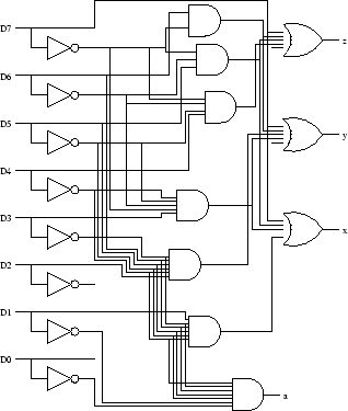
According to the previous table, ![]() and
and ![]() can de determined by the knowledge of all the
can de determined by the knowledge of all the ![]() .
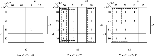
We also determine
.
We also determine ![]() , which is the equivalent for our neew circuit of the previous
, which is the equivalent for our neew circuit of the previous ![]() . The truth
table determining the first of our two combinational circuits follows.
. The truth
table determining the first of our two combinational circuits follows.
| Inputs | Outputs | |||||
| 0 | 0 | 0 | 0 | 0 | 1 | 1 |
| 0 | 0 | 0 | 1 | 0 | 1 | 1 |
| 0 | 0 | 1 | 0 | 0 | 1 | 1 |
| 0 | 0 | 1 | 1 | 0 | 1 | 1 |
| 0 | 1 | 0 | 0 | 0 | 1 | 1 |
| 0 | 1 | 0 | 1 | 0 | 1 | 1 |
| 0 | 1 | 1 | 0 | 0 | 1 | 1 |
| 0 | 1 | 1 | 1 | 0 | 1 | 1 |
| 1 | 0 | 0 | 0 | 0 | 1 | 0 |
| 1 | 0 | 0 | 1 | 0 | 1 | 0 |
| 1 | 0 | 1 | 0 | 0 | 1 | 0 |
| 1 | 0 | 1 | 1 | 0 | 1 | 0 |
| 1 | 1 | 0 | 0 | 0 | 0 | 1 |
| 1 | 1 | 0 | 1 | 0 | 0 | 1 |
| 1 | 1 | 1 | 0 | 0 | 0 | 0 |
| 1 | 1 | 1 | 1 | 1 | 0 | 0 |
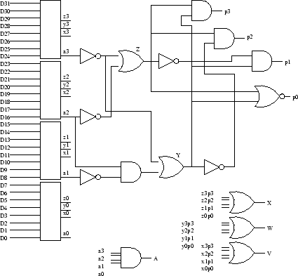
![]() is a variable telling us which encoder we should take the output from. Indeed, the value of
the sequence
is a variable telling us which encoder we should take the output from. Indeed, the value of
the sequence ![]() ,
,![]() , and
, and ![]() is exactly the value of the sequence
is exactly the value of the sequence ![]() ,
, ![]() , and
, and ![]() , respecitvely,
where
, respecitvely,
where ![]() can be determined from the knowledge of
can be determined from the knowledge of ![]() and
and ![]() . Once
. Once ![]() is calculated, all the
is calculated, all the ![]() 's
are ANDed with the output of the correspondent encoders. As the outputs of the encoders are directly
linked to
's
are ANDed with the output of the correspondent encoders. As the outputs of the encoders are directly
linked to ![]() ,
,![]() , and
, and ![]() , the latters will be reached by the right value only. This corresponds to the
use of a multiplexer using
, the latters will be reached by the right value only. This corresponds to the
use of a multiplexer using ![]() and
and ![]() as select lines and the outputs of the encoders as a multiple
input.
as select lines and the outputs of the encoders as a multiple
input.
| Inputs | Outputs | ||||
| 0 | 0 | 0 | 0 | 0 | 1 |
| 0 | 1 | 0 | 0 | 1 | 0 |
| 1 | 0 | 0 | 1 | 0 | 0 |
| 1 | 1 | 1 | 0 | 0 | 0 |
The last logic diagram uses a lot of intuitive notations. In particular, ![]() , for instance, shows
that the
, for instance, shows
that the ![]() and
and ![]() have been ANDed before reaching that point. Because of the feed back, the path
from the outputs of the encoders to
have been ANDed before reaching that point. Because of the feed back, the path
from the outputs of the encoders to ![]() ,
,![]() , and
, and ![]() should be lengthened by the use of non-inverter
for example. This is not shown on the diagram.
should be lengthened by the use of non-inverter
for example. This is not shown on the diagram.