


Next: Problem 5 - Logic
Up: Information Science I
Previous: Problem 3 - Regular
Consider the following design requirements of a sequence circuit using AND, OR, and NOT gate as well as
D flip-flop.
Requirements
It has a reset signal input and a counter signal input. It outputs a number from zero
to eight. When a reset signal is input, the output is reset to zero. When a counter
signal is input, the output changes in the following order: 0, 1, 3, 6, 7, 2. After that,
the output returns to zero, being in the same state as after a reset signal is input.
When both a reset signal and a counter signal are input at the same time, the reset signal
is effective.
- 1.
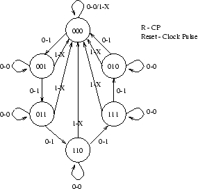
- Show the state transition diagram for this circuit. (Either the Mealy diagram or the Moore
diagram is fine.)
- 2.
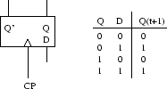
- Show the truth table of an input variable (a signal variable) of D flip-flop.
- 3.
- Show the logical formula optimized using a Karnaugh diagram or any other tableau method.
- 4.
- Show the whole circuit.
- 1.
- We are about to design a counter whose repeated sequence is:
The state transition diagram considers both the count pulses and the reset
signal as external inputs. X is a don't-care condition that expresses the
priority of the reset input over the count pulses.
- 2.
- A D flip-flop is also known as a data flip-flop. Indeed, no matter what the state of the flip-flop
was, after the occurrence of a count pulse, the flip-flop will be given the value of its D input,
as if it was only passing datas from its input to its output.
- 3.
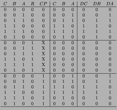
- To find out the logical formula and its eventual optimization, we first build the excitation table of
the designed counter. We design the three D flip-flops thanks to the letters
 ,
, , and
, and  , each
representing one bit of the state.
Each of the output can then be expressed as an optimzed Boolean function by means of the following Karnaugh
maps. We use the fact that we bever have
, each
representing one bit of the state.
Each of the output can then be expressed as an optimzed Boolean function by means of the following Karnaugh
maps. We use the fact that we bever have  and
and  as states, so that a large part of the Karnaugh maps
can be considered as a don't-care condition.
as states, so that a large part of the Karnaugh maps
can be considered as a don't-care condition.
- 4.
- The logic diagram is then derived from the form of the Boolean functions.
Next: Problem 5 - Logic
Up: Information Science I
Previous: Problem 3 - Regular
Reynald AFFELDT
2000-06-08

![\includegraphics[width=0.7\linewidth]{maps-counter.ps}](img1479.png)
![\includegraphics[width=0.7\linewidth]{logic-diagram-counter.ps}](img1480.png)